Industrial Biofilter Systems for Odor and VOC Control
ZSWT-series FRP biofilters (1K–100K, 1,000–100,000 m³/h) remove H₂S, NH₃, VOCs, and related odors through biofilm catabolism and anabolism—no continuous chemical oxidants, with optional integration to activated carbon, UV, scrubbers, or ion stages.
Send request
Biofilter design data for industrial odor and VOC control
Company background and product positioning
Guangdong Zhengzhou Environmental Protection Technology Co., Ltd. designs and supplies industrial biofilter systems that use attached microbial communities to remove biodegradable odorants from exhaust air. Equipment is selected from the measured airflow and load, required residence time, media condition, moisture and pH control, available footprint, and outlet target.
Biofilter operating principle
Microbial cultivation and biofilm formation
Humidified gas passes through a porous medium where heterotrophic and chemolithotrophic organisms colonize surfaces, forming a stable biofilm with sufficient moisture and nutrients for sustained activity.
Biodegradation of contaminants
Odorants diffuse into the biofilm and are metabolized to simpler, less odorous or mineral end products under aerobic conditions, with mass transfer controlled by residence time, media depth, and partition coefficients.
Key treatment mechanisms
- Catabolism—oxidation of organic and reduced inorganic species to extract energy for the cell.
- Anabolism—assimilation of carbon and nutrients into biomass within the filter matrix.
End products
- Water (vapor and liquid phase within the bed)
- Carbon dioxide (from mineralization of organics and some sulfur species)
- Harmless mineralized residues and stable biomass (managed via periodic media replacement and leachate handling)
Technical introduction
Process workflow
Odor inlet → Pre-treatment zone (humidification / dust or droplet removal as required) → Bio-filtration zone → De-watering / mist elimination zone → clean air outlet.
Microbial treatment mechanisms
- Catabolism of substrates supplied by the waste gas stream
- Anabolic growth maintaining biofilm thickness and activity
- Oxidation pathways for reduced sulfur, nitrogen, and organic species under controlled O₂ and moisture
Target pollutants
- Sulfur compounds (H₂S, CH₃SH, SO₂, mercaptans)
- Nitrogen compounds (NH₃, amines)
- Organic compounds (VOCs, aldehydes, ketones)
- Methane (CH₄)—removal efficiency depends on specialized consortia and design; often combined with other stages for low-concentration applications
Typical removal efficiency bands
| Pollutant group | Indicative efficiency |
|---|---|
| Sulfur species | 85–95% |
| Nitrogen species | 80–90% |
| Organic compounds | 80–92% |
| Methane (CH₄) | 70–85% (design- and consortium-dependent) |
Product classification
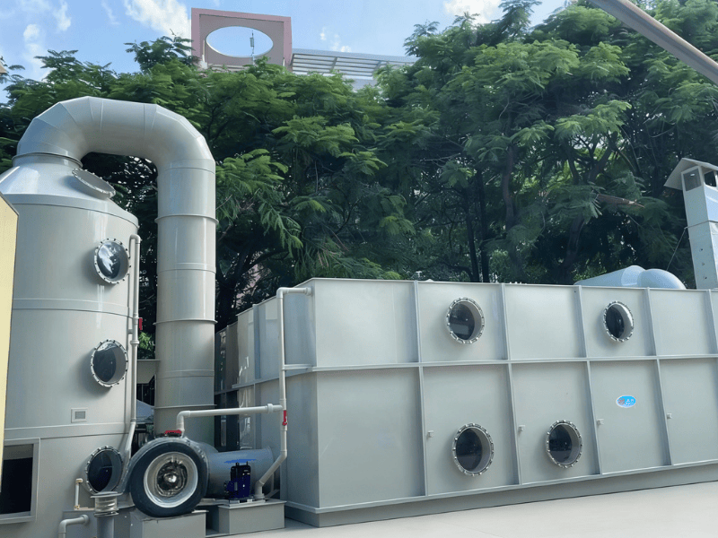
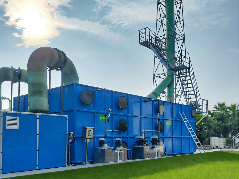
ZSWT series biofilter models (FRP construction)
Model range: ZSWT-1K through ZSWT-100K. Flow range: 1,000–100,000 m³/h.
Typical parameters: overall dimensions (L × W × H), shell thickness, inlet/outlet connections, filter media bed depth, circulation pump power, water tank size, inoculum / culture mass, and pressure drop.
| Model | Flow (m³/h) | L×W×H (typ.) | Thickness | Inlet / outlet | Media depth | Pump | Tank | Inoculum | ΔP (ref.) |
|---|---|---|---|---|---|---|---|---|---|
| ZSWT-1K | 1,000 | Per design | 6–8 mm | Matched to duct | Per design | Per duty | Per design | Per design | 600–800 Pa (ref.) |
| ZSWT-10K | 10,000 | Per design | 6–10 mm | Matched to duct | Per design | Per duty | Per design | Per design | 600–800 Pa (ref.) |
| ZSWT-25K | 25,000 | Per design | 8–10 mm | Matched to duct | Per design | Per duty | Per design | Per design | 600–800 Pa (ref.) |
| ZSWT-50K | 50,000 | Per design | 8–12 mm | Matched to duct | Per design | Per duty | Per design | Per design | 600–800 Pa (ref.) |
| ZSWT-100K | 100,000 | Per design | 8–12 mm | Matched to duct | Per design | Per duty | Per design | Per design | 600–800 Pa (ref.) |
Intermediate models follow the same families; certified drawings and datasheets are issued per project.
Material options
- FRP (fiberglass)
- Stainless steel (SS304 / SS316)
- PP / PPS plastics
Applicable temperature range
Standard engineered beds are commonly operated with gas temperatures in the 10–40°C range; short excursions may be acceptable with material and insulation upgrades. Sub-freezing or high-temperature streams require pre-conditioning and material review.
Corrosion resistance comparison (qualitative)
| Material | Acid / alkaline wet gas | Remarks |
|---|---|---|
| FRP | Excellent for many H₂S / humid odorous streams | Resin grade matched to chemistry |
| SS304 / SS316 | Very good; 316 for chloride-rich duties | Hygiene and high structural strength |
| PP / PPS | Good chemical resistance in many VOC / mist services | Temperature limits per polymer grade |
Setting configuration and structure
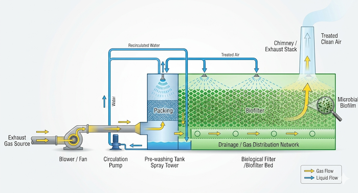
Equipment structure
- Pre-treatment / scrubbing zone (humidification, dust removal, conditioning)
- Bio-purification zone (packed media with active biofilm)
- De-watering zone (droplet capture before discharge)
- Spray / circulation system (nutrient and moisture management)
Standard configuration
- Tower / vessel shell
- Pre-wash section (when specified)
- Biological filter media layers
- De-watering layer
- Water tank and circulation pump
- Control panel
- Access doors / manways for inspection
Installation configuration types
- Single-unit configuration
- Parallel units for redundancy or capacity
- Multi-stage biological trains
- Combined systems with polishing stages (e.g. carbon, scrubber)
Material selection
Primary structural materials (typical thickness bands)
- FRP: about 6–10 mm (laminate schedule per diameter and pressure)
- Stainless steel 304: about 1.2–2.0 mm (sheet) plus stiffeners as required
- Stainless steel 316: about 1.2–2.0 mm for aggressive or chloride services
- PP / PPS: about 8–12 mm (welded / molded construction per design code)
Filter media types
- Organic composite media (wood chips, bark blends, compost-based)
- Inorganic media (expanded clay, lava rock, engineered ceramics)
- Synthetic engineered media
- Hybrid / layered mixed beds
Filter media service life (indicative)
- Organic composite: 3–5 years
- Inorganic: 5–8 years
- Synthetic: 8–10 years
- Mixed beds: 5–7 years
Selection criteria
- Gas temperature and dew point
- Chemical composition and peak loads
- Humidity level and water balance
- Budget and lifecycle cost targets
- Ease of maintenance and media change-out
Technical characteristics
Performance parameters (design reference)
- Purification efficiency: ≥ 92% for specified odor / VOC targets (inlet-dependent)
- Superficial velocity (empty bed): 0.5–1.5 m/s
- Gas residence time in media: 15–60 s (typical)
- Pressure drop: about 600–800 Pa (clean / design point)
- Operating temperature: 10–40°C (standard range)
- Relative humidity in bed: 40–60% (controlled via pre-humidification)
- pH of leachate / irrigation: 6.5–7.5 (buffered as required)
Microbial characteristics
- Bacterial and fungal consortia selected for target pollutants (e.g. Thiobacillus spp. for sulfur)
- Inoculation and acclimation period defined per startup protocol
- Biofilm thickness managed by shear, irrigation, and organic load
- Effective microbial activity over months to years with proper nutrition
- Temperature tolerance aligned with 10–40°C operating window (strain-dependent)
- pH tolerance typically near neutral; shock loads avoided by pre-treatment
System design parameters
- Filter media depth and sectional layout
- Gas residence time and empty-bed contact time
- Moisture content and irrigation schedule
- Nutrient dosing ratio (N, P, trace elements) relative to organic load
- Pressure drop limits for fan selection
- Air distribution plenum and flow uniformity
- Heating or insulation for cold climates
Main features and advantages
Core features
- High efficiency (≥ 92% purification for many odor applications when properly designed)
- Economical energy use versus thermal oxidizers for dilute streams
- No continuous chemical oxidant addition (nutrients only, as needed)
- Single inoculation / acclimation with stable operation thereafter
- Environmental profile: biodegradation pathway, controlled leachate
- Multiple microbial guilds for broad-spectrum odor treatment
- Relatively short commissioning cycle after acclimation
- Open-structured media with low head loss when clean
- Compact modular footprints available
- Low noise fans and simple mechanical auxiliaries
- Straightforward operation after training
- Accessible maintenance via doors and sampling ports
Advantage comparison
- High treatment efficiency for biodegradable odors
- Lower OPEX than combustion for low-concentration exhausts
- Favorable environmental footprint
- Long equipment life with correct materials
- Broad applicability across municipal and industrial sources
- Stable performance when load is managed
- Moderate maintenance demand (scheduled inspections)
- Effective odor reduction for community-sensitive sites
- Automatable irrigation, fans, and alarms
- Corrosion-resistant material options for wet services
Cost–benefit comparison (typical themes)
| Factor | Biofilter perspective |
|---|---|
| Capital investment | Competitive for large air volumes vs. thermal oxidation |
| Operating cost | Mainly fan power, pumping, and nutrient / water makeup |
| Maintenance cost | Periodic media replacement and nozzle service |
| Energy use | Lower than RTO for dilute streams |
| Chemical cost | Minimal vs. chemical scrubbing |
| Waste handling | Spent media and leachate per site environmental plan |
Application fields
Industry applications
- Wastewater treatment plants
- Open tanks and covered basins
- Waste transfer stations
- Filter and reaction tank vents
- Paint / coating facilities
- Livestock and poultry farms
- Rubber and plastics processing
- Food and beverage plants
- Feed mills
- Pharmaceutical manufacturing
- Laboratories
- Composting and organics recycling
Pollutant treatment capability
- Hydrogen sulfide
- Ammonia
- Methyl mercaptan and other mercaptans
- Methane (with appropriate design expectations)
- VOCs
- Aldehydes
- Ketones
- Organic acids
- Amines
Project evidence
Named reference projects are published only when airflow, configuration and client-name usage can be checked against the project file. For a relevant reference package, send the application, airflow and target pollutants through the engineering enquiry form.
Applicable standards (reference)
- GB 16297-1996 — Integrated emission standards of air pollutants
- GB 14554-93 — Emission standards for odor pollutants
- GB 3095-2012 — Ambient air quality standards
- DB 44/27-2001 — Guangdong provincial air emission limits (regional reference)
System integration options
Combined treatment trains
- Biofilter + activated carbon (polishing)
- Biofilter + UV photolysis / oxidation
- Biofilter + wet scrubber (pre-conditioning or acid gas removal)
- Biofilter + high-energy ion stage
- Multi-stage biofilters in series for difficult loads
Control system functions
- PLC-based control and interlocking
- Bed humidity / irrigation monitoring
- Temperature monitoring and alarms
- Differential pressure monitoring across media
- Alarm and fault annunciation
- Remote access (optional)
- Data logging for compliance and troubleshooting
Maintenance guidelines
Routine maintenance plan
| Task | Suggested frequency |
|---|---|
| Nozzle inspection (spray pattern, clogging) | Monthly |
| Sump / tank water level | Weekly |
| pH monitoring (leachate / irrigation) | Weekly |
| Pressure drop check | Monthly |
| Media inspection (channeling, compaction) | Quarterly |
| Microbial activity assessment (e.g. CO₂, odor spot checks) | Semi-annual |
| Full system inspection (structural, instruments, safety) | Annual |
| Media replacement | Condition-based: pressure drop, compaction, channeling and biological performance |
Operational best practices
- Maintain design moisture content in the bed without flooding
- Keep inlet temperature within agreed limits; avoid thermal shock
- Track pH and nutrient status; adjust dosing with engineering guidance
- Ensure even airflow distribution via plenum and media leveling
- Protect the biofilter from toxic spikes (e.g. biocides, solvents) via upstream control
- Provide adequate nutrient supply for sustained biomass activity
- Inspect spray headers and pumps on a fixed schedule
- Keep maintenance and media change-out records for audits