Catalytic combustion equipment for VOC oxidation and elimination
ZZCO and ZZZW-series systems destroy VOCs through catalytic oxidation at 300–400°C with heat recovery—integrated with adsorption or zeolite concentration for medium- to large-volume exhaust from coating, printing, chemical, and pharma operations.
Send request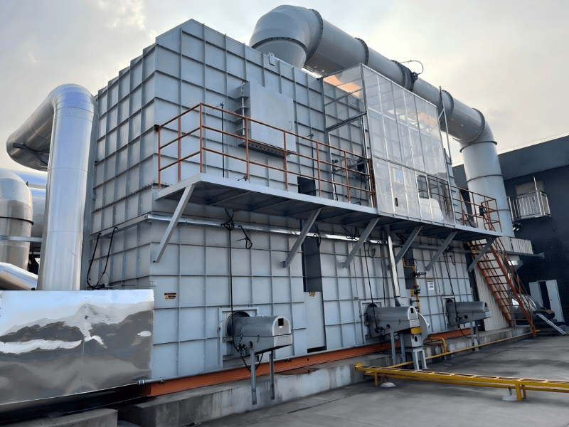
Catalytic combustion for VOC oxidation and elimination
Guangdong Zhengzhou Environmental Protection Technology Co., Ltd. supplies catalytic oxidation systems that destroy volatile organic compounds (VOCs) at temperatures far below conventional thermal oxidizers. Equipment is engineered for airflow, concentration profiles, safety limits, and integration with adsorption or concentration front ends.
Catalytic combustion overview
Lowering activation energy
Supported noble- or base-metal catalysts provide active surfaces that reduce the energy barrier for oxidation, enabling sustained reaction at moderate temperatures while maintaining high destruction efficiency.
Low-temperature complete oxidation
VOCs and oxygen react on the catalyst to form carbon dioxide and water vapor with recoverable heat, avoiding the very high furnace temperatures typical of straight thermal oxidation.
Key treatment process
- VOCs are concentrated or released from activated carbon (or zeolite) during controlled desorption.
- The desorbed stream enters the catalytic reactor for oxidation on the catalyst bed.
- Products are primarily CO₂ and H₂O, with sensible heat available for recovery.
System types
- CO catalytic oxidation—suited to medium-concentration VOC streams after pretreatment and, where needed, upstream concentration.
- Zeolite rotor + CO / RTO—for large-volume, low-concentration exhaust; the rotor concentrates VOCs before oxidation in CO or regenerative thermal oxidation.
Custom engineering
Layouts, materials, heat recovery, safety instrumented functions, and tie-ins to existing ducts or adsorption trains are tailored to site utilities, permit limits, and operational duty.
Technical introduction
Process workflow
VOC exhaust → Pre-filtration → Heat exchanger → Heating section → Catalytic chamber → Heat recovery → clean air discharge.
Catalytic oxidation stages
- Preheat—typically 200–300°C (approach to catalyst light-off).
- Catalytic reaction—300–400°C on the active bed.
- Heat recovery—outlet gas often 150–250°C when exchangers are applied.
- Cooling / stack—final discharge commonly 40–80°C after recovery and trim cooling.
Reaction equation (simplified)
VOCs + O₂ → (catalyst, 300–400°C) → CO₂ + H₂O + heat
Target pollutants
- Aromatics (benzene, toluene, xylene)
- Alcohols (methanol, ethanol, isopropanol)
- Ketones (acetone, MEK)
- Esters (ethyl acetate, butyl acetate)
- Aldehydes (formaldehyde, acetaldehyde)
- Hydrocarbons (alkanes, alkenes, aromatics)
Indicative removal efficiency
| Group | Efficiency band |
|---|---|
| Aromatics | 95–98% |
| Alcohols | 93–96% |
| Ketones | 94–97% |
| Esters | 93–96% |
| Aldehydes | 92–95% |
| Hydrocarbons | 94–97% |
Product classification
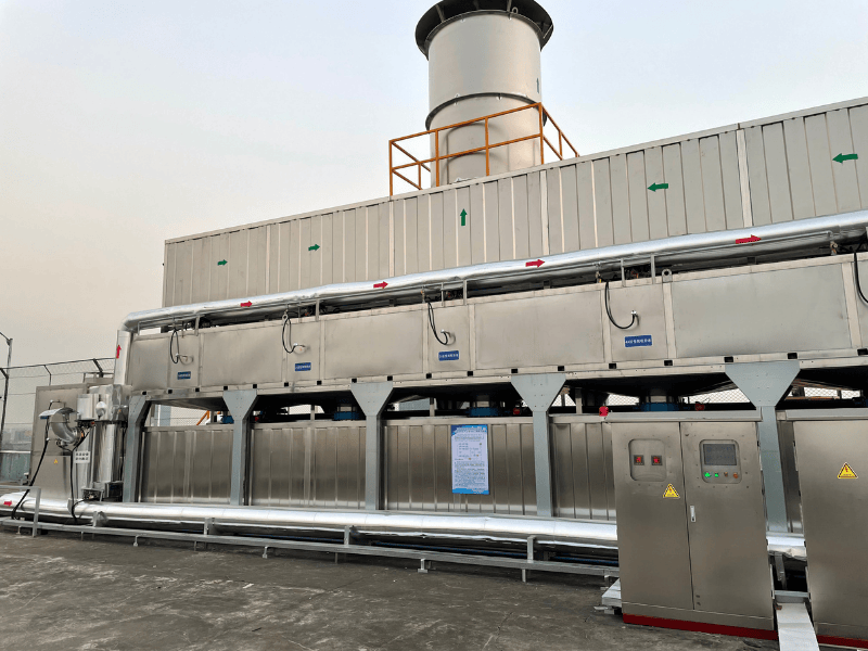
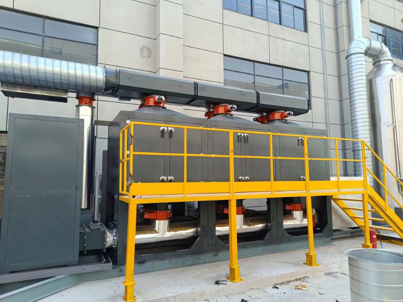
ZZCO series — catalytic oxidation (CO)
Model span: 2K–50K class. Flow range (reference): 2,000–60,000 m³/h. Certified datasheets are issued per project.
| Model | Flow (m³/h) | Footprint (typ.) | Power | Bed temp. | Catalyst | ΔP (ref.) |
|---|---|---|---|---|---|---|
| ZZCO-2K | 2,000 | Per design | Per duty | 300–400°C | Honeycomb ceramic | 800–1,200 Pa |
| ZZCO-5K | 5,000 | Per design | Per duty | 300–400°C | Honeycomb ceramic | 800–1,200 Pa |
| ZZCO-10K | 10,000 | Per design | Per duty | 300–400°C | Honeycomb / zeolite | 800–1,200 Pa |
| ZZCO-20K | 20,000 | Per design | Per duty | 300–400°C | Honeycomb / zeolite | 800–1,200 Pa |
| ZZCO-30K | 30,000 | Per design | Per duty | 300–400°C | Honeycomb / zeolite | 800–1,200 Pa |
| ZZCO-50K | 50,000 | Per design | Per duty | 300–400°C | Per spec | 800–1,200 Pa |
ZZZW series — zeolite rotor + CO / RTO
Model span: 10K–100K class. Flow range (reference): 10,000–150,000 m³/h. Concentration ratio, rotor speed, and desorption temperature are matched to solvent load and safety limits.
| Model | Flow (m³/h) | Conc. ratio | Footprint | Power | Rotor | Desorption T |
|---|---|---|---|---|---|---|
| ZZZW-10K | 10,000–30,000 | 8–15× | Per design | Per duty | Per design | 180–220°C |
| ZZZW-25K | 25,000–60,000 | 8–15× | Per design | Per duty | Per design | 180–220°C |
| ZZZW-50K | 50,000–100,000 | 8–20× | Per design | Per duty | Per design | 180–220°C |
| ZZZW-100K | 100,000–150,000 | 8–20× | Per design | Per duty | Per design | 180–220°C |
Catalyst formats
- Honeycomb ceramic catalysts
- Metal-mesh supported catalysts
- Activated-carbon-supported formulations (where applicable to process)
- Zeolite-supported catalysts
Catalyst life comparison (indicative)
| Type | Typical life |
|---|---|
| Honeycomb ceramic | 3–5 years |
| Metal mesh | 4–6 years |
| Activated-carbon-supported | 2–4 years |
| Zeolite-supported | 5–8 years |
Setting configuration and structure
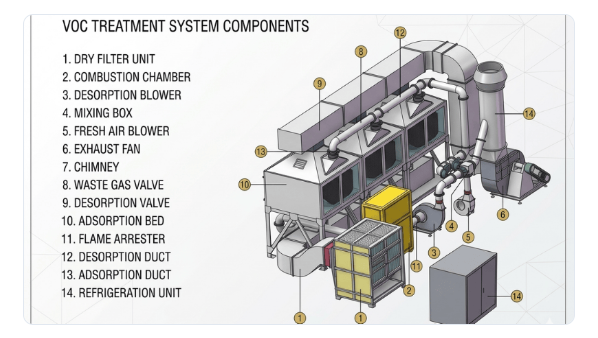
Equipment structure
- Pretreatment section (filtration / mist removal as required)
- Heat exchange section
- Heating chamber
- Catalytic reactor
- Post-treatment / stack section
Standard configuration
- Main casing — carbon steel with coating or stainless steel
- Pre-filters — G4 / F7 classes per dust loading
- Heat exchanger — plate type, 60–80% thermal effectiveness (design-dependent)
- Heating — electric or gas burner trains
- Catalyst bed — honeycomb or specified geometry
- Control — PLC + touchscreen HMI
- Safety — flame arrestors, pressure relief, high-temperature alarms
- Fan train, stack, and continuous sensors (T, P, LEL as applicable)
Installation arrangements
- Single unit—typically up to ~30,000 m³/h (project-specific).
- Parallel units—for higher flow or redundancy.
- Multi-stage systems—pretreatment + oxidation + polishing.
- Integrated trains—zeolite + CO, zeolite + RTO, or adsorption-desorption-catalysis packages.
Material selection
Main structure
- Carbon steel + coating (2.0–3.0 mm typical)
- Stainless 304 (1.5–2.5 mm)
- Stainless 316 (1.5–2.5 mm)
- FRP (6–10 mm) for corrosive service
Catalyst chemistry
- Precious metal (Pd, Pt)
- Base metal (Cu, Mn, Co)
- Mixed-metal formulations
- Special recipes for halogenated or sulfur-bearing streams (case-by-case)
Insulation
- Ceramic fiber (50–100 mm; up to ~1,000°C rating)
- Rock wool (50–80 mm; ~600°C class)
- Glass wool (40–60 mm; ~400°C class)
Selection criteria
Gas temperature, chemical composition, corrosion potential, capital and operating budget, maintenance access, and safety/regulatory requirements drive casing alloy, gasket materials, insulation thickness, and catalyst choice.
Technical characteristics
Performance parameters
- Destruction efficiency — ≥95% (design basis)
- Operating temperature — 300–400°C on catalyst
- Heat recovery — 60–80% (configuration-dependent)
- Pressure drop — 800–1,200 Pa (typical range)
- Catalyst space velocity — 10,000–30,000 h⁻¹
- Start-up — 15–30 minutes to stable operation
- Power — 15–260 kW (duty-dependent)
Catalyst properties (indicative)
- Active surface area — 200–400 m²/g
- Light-off — 250–300°C
- Short-term maximum — ~600°C
- Thermal shock resistance — 100+ cycles (design-dependent)
- Crush strength — >15 MPa
- Service life — 3–8 years with proper operation
System design inputs
- VOC concentration range and variability
- Inlet gas temperature
- Particulate loading
- Catalyst bed depth and residence time
- Oxygen availability
- Humidity limits
Safety parameters
- LEL monitoring — maintain <25% LEL in oxidizer feed (typical project rule)
- Temperature alarms — high (~450°C) and low (~250°C) strategy per interlock philosophy
- Pressure relief — e.g. 2,000 Pa automatic relief (set per code)
- Flame arrestors on vulnerable lines
- Emergency shutdown and optional fire-suppression interfaces
Main features and advantages
Core features
- High efficiency (≥95% DRE target for many VOCs)
- Energy saving via 60–80% heat recovery
- Moderate temperature operation (300–400°C vs. 700–800°C thermal)
- Layered safety (LEL, temperature, pressure, ESD)
- Compact footprint versus conventional RTO/TO for comparable duty (often 70–80% less area)
- Moderate pressure drop (800–1,200 Pa)
- Long catalyst life with correct operation (3–8 years)
- PLC + HMI automation
- No secondary organic waste stream — CO₂ and H₂O as primary products
- Broad solvent applicability; 15–30 minute warm-up; straightforward maintenance access
Advantage themes
High treatment efficiency, favorable energy balance, environmental compliance, durable components, wide application range, stable operation, moderate maintenance, safe interlocks, automated operation, compact layout, competitive operating cost, and alignment with emission standards.
Cost and energy comparison
- CAPEX / OPEX / maintenance—evaluated per project against concentration, hours, and utility costs.
- Energy—thermal oxidation often 700–800°C; catalytic 300–400°C → ~50–60% fuel savings; add heat recovery for another ~40–50% savings on recovered duty.
- Combined savings—order-of-magnitude 70–80% total energy reduction versus unrecovered thermal oxidation in comparable cases.
- Payback—simple returns often 1.5–3 years when energy and solvent recovery credits apply.
Consumables and waste
Power, fuel or electricity for heating, catalyst replacement cycles, filter media, and inspection labor are the main recurring items; spent catalyst is handled per local hazardous/non-hazardous waste rules.
Application fields
Industries
- Surface coating (spray booths, drying ovens)
- Printing (flexo, gravure)
- Chemicals (reactors, tank vents)
- Pharmaceutical (production, solvent recovery vents)
- Electronics (PCB cleaning, coating)
- Automotive (paint shops, parts cleaning)
- Furniture (wood finishing)
- Packaging (flexible packaging, lamination)
- Textiles (coating, dyeing)
- Rubber and plastics (forming, extrusion)
- Food (flavoring, extraction)
- Semiconductors (wafer cleaning, lithography ancillaries)
VOC classes handled
- Aromatics, alcohols, ketones, esters, aldehydes
- Chlorinated VOCs (TCE, PCE) — specialized catalyst and safety review
- Alkanes (hexane, heptane, octane)
- Glycol ethers
Reference projects
| Project name | Location | Flow rate (m³/h) | Application | Year | System type |
|---|---|---|---|---|---|
| Shaanxi Tongchuan New Materials | Shaanxi | 80,000 | Catalyst manufacturing | 2022 | Zeolite + CO + Spray Tower + High-Energy Ion |
| Foshan Sanshui Leiping Packaging | Foshan | 8,000 | Packaging printing | 2022 | Catalytic Combustion + Fan |
| Foshan Sanshui Duozheng Resin | Foshan | 5,000 | Resin production | 2021 | Catalytic Combustion + Fan |
| Jiangsu Yancheng Dongshan Precision | Jiangsu | 10,000 | Electronics manufacturing | 2023 | Zeolite + Catalytic Combustion + Spray Tower + Fan |
| Xi'an Kaili New Materials | Xi'an | 40,000 | Catalyst production | 2023 | Catalytic Hydrogenation Workshop |
| Xi'an Kaili Innovation Center | Xi'an | 500,000 | R&D facility | 2023 | VOCs Treatment Project |
Applicable standards
- GB 16297-1996 — Integrated emission standard of air pollutants
- GB 37822-2019 — VOC fugitive emission control standard
- GB 3095-2012 — Ambient air quality standard
- Local DB standards and sector guidelines as applicable
Pretreatment requirements
- Particulates — typically <5 mg/m³ at oxidizer inlet
- Temperature — commonly <80°C at adsorber/oxidizer boundary unless designed otherwise
- Humidity — control <80% RH where required to protect adsorbent or catalyst
- Poison avoidance — limit heavy metals, halogens, S, As, P per catalyst warranty
- VOC concentration within design envelope; oxygen >15% for stable oxidation
System integration options
Combined treatment trains
- Pre-filtration + CO
- Spray tower + CO
- Activated carbon (adsorption / desorption) + CO
- Zeolite rotor + CO
- Zeolite rotor + RTO
- Multi-stage CO or hybrid polishing
Control system functions
- PLC logic, touchscreen HMI, temperature and pressure control
- LEL monitoring, alarms, data logging, auto start/stop sequences
- Remote access (optional), emergency stop, permissive interlocks
Maintenance guidelines
Routine plan
- Weekly — pre-filter inspection
- Monthly — temperature sensors, differential pressure review
- Quarterly — catalyst bed visual / sample port checks
- Semi-annual — heating elements, safety system functional tests
- Annual — full system audit, catalyst activity test
- 3–8 years — catalyst replacement per performance and vendor guidance
Operating best practices
- Hold inlet temperature and VOC concentration within design
- Track bed temperatures and pressure drop trends
- Avoid poisons and particulate breakthrough; maintain oxygen
- Change prefilters on schedule; log service; train operators; stock critical spares
Catalyst care
| Recommended | Avoid |
|---|---|
| Operate within specified temperature band; maintain pretreatment; prevent poisons; periodic activity testing; dry, clean storage for spare charges. | Chronic over-temperature; particulate overload; exposure to catalyst poisons; ignoring performance decline; wet or contaminated storage. |
Figures and tables summarize typical ranges; certified drawings, P&IDs, and interlock matrices are provided for each contract.