Industrial wet scrubber for acid gas and pollutant neutralization
Industrial wet scrubbers (ZZPLT spray and ZZQXT cyclone-hybrid series) remove particulates, acid/alkaline gases, and soluble contaminants through impaction and absorption—engineered for low pressure drop, low energy use, and project-specific materials from FRP to stainless steel.
Send request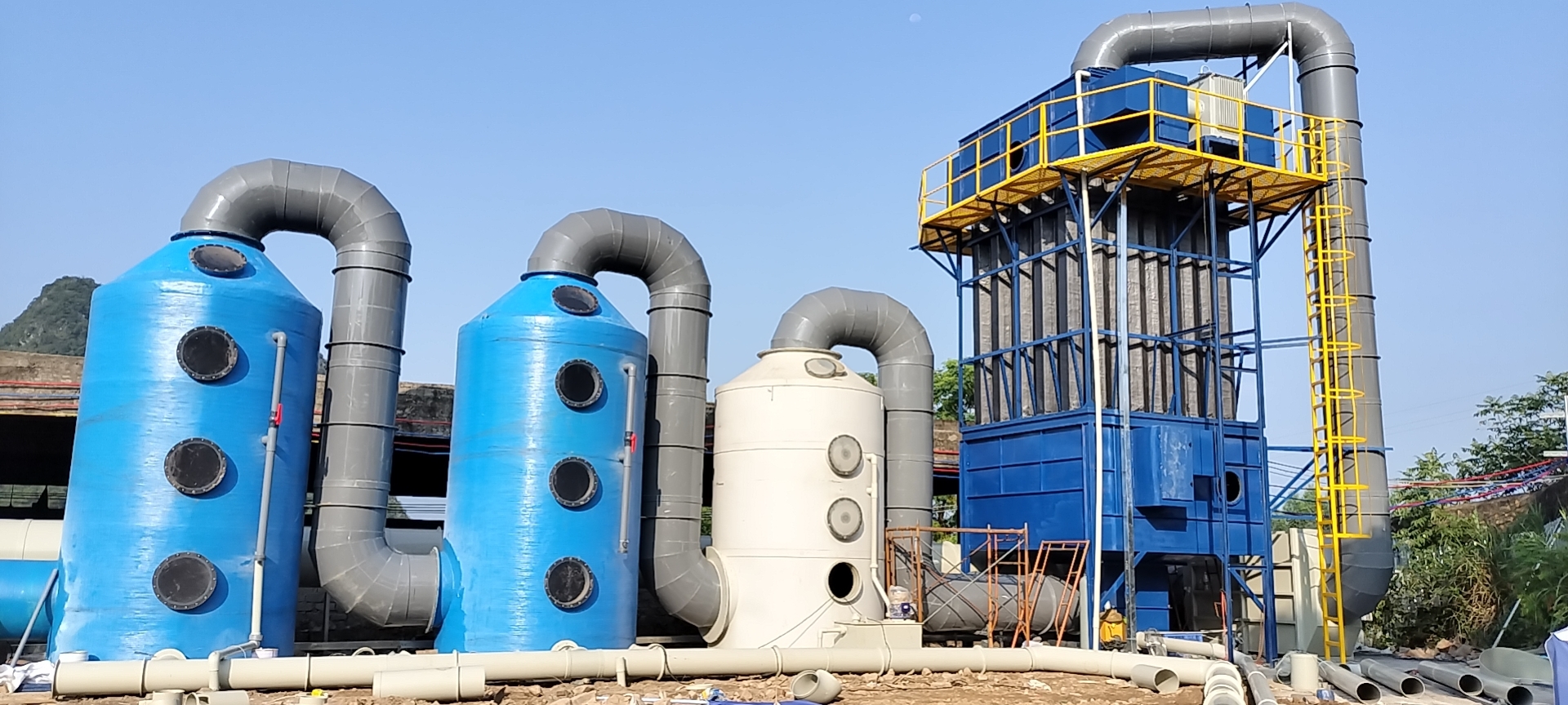
Industrial wet scrubber for acid gas and pollutant neutralization
Company background and product positioning
Guangdong Zhengzhou Environmental Protection Technology Co., Ltd. supplies industrial wet scrubber systems engineered for high-efficiency gas purification across plant scales. Equipment is sized and configured to match process airflow, pollutant loading, and compliance targets—from compact workshop lines to large central exhaust trains.
Applicable pollutant types
- Particulate matter and toxic contaminants
- Inorganic fumes, vapors, and gases
Typical target species include:
- Chromic acid
- Hydrogen sulfide
- Ammonia
- Chlorides
- Fluorides
- Sulfur dioxide (SO₂)
System design advantages
- Low pressure-drop layouts to reduce fan power
- Energy-conscious spray, packing, and circulation design
Pollutant removal principles
- Inertial impaction—droplets and wetted surfaces capture particles and droplet-borne contaminants.
- Physical absorption—mass transfer of soluble gases into the scrubbing liquid.
- Chemical absorption (when specified)—neutralization or reaction in the liquid phase for acidic/alkaline or oxidizable species.
Custom engineering
Tower diameter, height, number of stages, material grade, pump duty, and instrumentation are selected from site data: gas flow, temperature, humidity, dust load, and required outlet concentration. We provide drawings and operating limits for each project.
Product classification
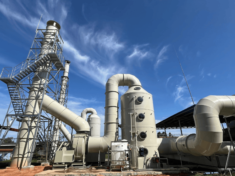
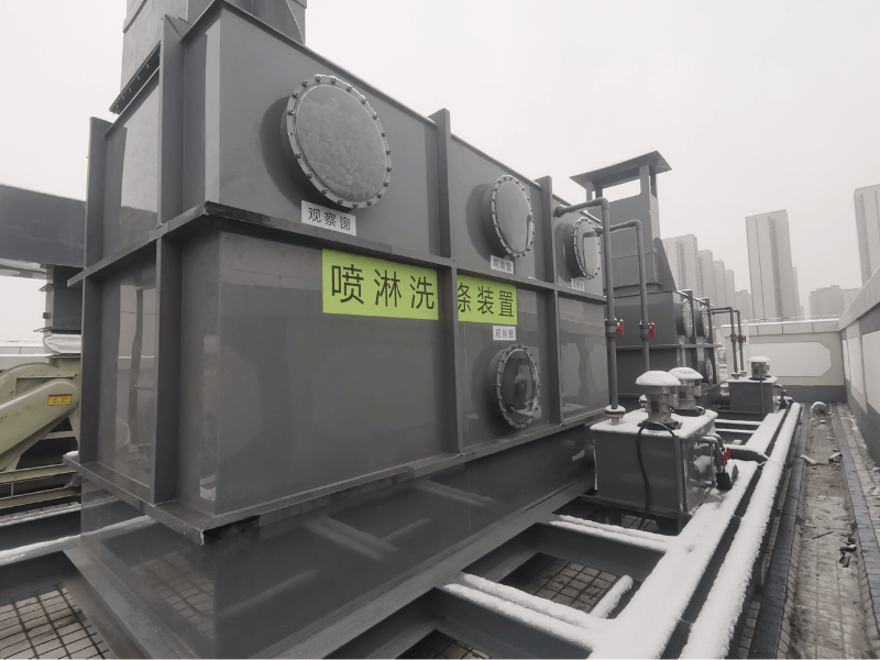
Spray scrubber series (ZZPLT)
Model range: ZZPLT-2K through ZZPLT-100K (e.g. 2K, 5K, 10K, 15K, 20K, 25K, 30K, 35K, 40K, 50K, 60K, 80K, 100K).
Flow range: 2,000–100,000 m³/h. Typical parameters: tower dimensions, sump/tank volume, shell thickness, circulation pump power, inlet/outlet connections, and system resistance (commonly about 400–800 Pa, subject to design).
| Model | Flow (m³/h) | Tower (typ.) | Sump / tank | Thickness | Pump | Inlet / outlet | ΔP (ref.) |
|---|---|---|---|---|---|---|---|
| ZPLT-2K | 2,000 | Φ700 × 3,600 mm | 700×500×500 mm | 6 mm | 0.37 kW | Φ250 mm | 500 Pa |
| ZPLT-4K | 4,000 | Φ950 × 4,200 mm | 750×500×500 mm | 6 mm | 0.75 kW | Φ355 mm | 500 Pa |
| ZPLT-10K | 10,000 | Φ1,400 × 4,200 mm | 750×500×500 mm | 6 mm | 2.2 kW | Φ500 mm | 500 Pa |
| ZPLT-20K | 20,000 | Φ2,200 × 5,200 mm | 800×600×600 mm | 10 mm | 5.5 kW | Φ700 mm | 500 Pa |
| ZPLT-50K | 50,000 | Φ3,500 × 6,000 mm | 1,000×800×750 mm | 12 mm | 15 kW | Φ1,200 mm | 500 Pa |
Intermediate models follow the same parameter families; exact dimensions are issued per quotation and GA drawings.
Cyclone hybrid spray scrubber series (ZZQXT)
Model range: ZZQXT-01K through ZZQXT-12K.
Flow range: 7,000–60,000 m³/h. Typical parameters: tower body, cyclone barrel dimensions, material thickness, circulation pump, inlet/outlet, and pressure loss.
| Model | Flow (m³/h) | Tower (typ.) | Cyclone barrel | Thickness | Pump | Inlet / outlet | ΔP (ref.) |
|---|---|---|---|---|---|---|---|
| ZZQXT-01K | 7,000 | Per design | Per design | 6–10 mm | Per duty | Matched to duct | Per design |
| ZZQXT-04K | 20,000 | Per design | Per design | 8–12 mm | Per duty | Matched to duct | Per design |
| ZZQXT-08K | 40,000 | Per design | Per design | 10–12 mm | Per duty | Matched to duct | Per design |
| ZZQXT-12K | 60,000 | Per design | Per design | 10–15 mm | Per duty | Matched to duct | Per design |
Column / stage types (by internals)
- Perforated tray columns
- Packed (random packing) columns
- Spray washing columns
Functioning and operation
Process flow (narrative)
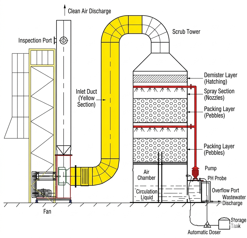
Gas path: Inlet → pre-conditioning (if any) → spray / packing contact zone(s) → demister → outlet stack or fan suction.
Liquid path: Sump → circulation pump → spray headers / distributors → contact zone → return to sump with bleed, makeup, and chemical dosing as designed.
Formal P&ID and process flow diagrams are issued with each project package.
Three design requirements for effective purification
- Sufficient contact time and interfacial area—via spray density, packing height, and stage count matched to kinetics and solubility.
- Appropriate L/G ratio and liquor chemistry—to meet outlet concentration without excessive scaling or corrosion.
- Reliable mist elimination—to prevent re-entrainment and stack droplet carryover.
Operating sequence
- Pre-start: Verify sump level, pump rotation, nozzle cleanliness, demister condition, instrumentation, and interlocks.
- Start-up: Establish circulation, stabilize chemistry, then introduce process gas per ramp procedure.
- Running: Monitor ΔP, levels, pH/conductivity (if fitted), pump current, and stack indicators.
- Shutdown: Stop gas inlet per SOP, flush if required, stop pumps, isolate drains safely.
- Maintenance cycle: Scheduled inspection of packing, nozzles, demister, pump seals, and instrumentation calibration.
Treatable pollutants (summary list)
- Chromic acid mist
- Hydrogen sulfide (H₂S)
- Ammonia (NH₃)
- Chlorides and acidic halogen gases
- Fluorides
- Sulfur dioxide (SO₂)
- Acidic and alkaline mists
- Soluble VOCs (where scrubbing liquid is selected accordingly)
- Dust and fine particulate (with appropriate stage design)
- Odorous inorganic gases (with oxidizing or neutralizing liquor)
System schematic
Setting configuration
Installation arrangement
- Vertical (upright) scrubbers
- Horizontal scrubbers (where headroom or layout requires)
Washing stages
- Single-stage washing
- Two-stage washing
- Three-stage washing (including 35CR-type configurations)
System components
- Scrubber vessel / tower shell
- Spray layers (nozzles, headers, and distribution)
- Packing layers (when applicable)
- Demister / mist elimination section
- Circulation pump(s)
- Sump or external tank
- Control panel / local controls
- Manways for inspection and maintenance
Material selection
Primary materials
- FRP (fiberglass reinforced plastic)
- PP (polypropylene)
- PVDF (polyvinylidene fluoride)
- Stainless steel (SS304 / SS316)
- Carbon steel with corrosion-resistant coating
Typical shell thickness bands
- Small units: about 6 mm
- Medium units: about 8–10 mm
- Large units: about 10–12 mm
- Extra-large units: about 12–15 mm
Packing media (examples)
- Hollow balls
- Raschig rings
- Pall rings
- Berl saddles
Wash solution system
Liquor types
- Acidic liquor—for alkaline gases (e.g. ammonia).
- Alkaline liquor—for acidic gases (e.g. SO₂, acid mists).
- Oxidizing chemistry—for deodorization and disinfection where specified.
Automation and level control
- ARRS—automatic reagent replenishment
- AWRS—automatic makeup water
- Three-point liquid level control for safe operation and pump protection
Circulation process
Scrubbing liquid is drawn from the sump, pressurized through the circulation pump, distributed to spray headers (and/or wetting of packing), contacts the gas stream, and returns to the sump for concentration monitoring, blowdown, and chemical dosing as required.
Pump sizing reference
| Indicative flow band (m³/h) | Typical circulation pump (reference) |
|---|---|
| 2,000–10,000 | 0.75–4 kW class, head per hydraulic layout |
| 10,000–40,000 | 4–11 kW class, redundant options available |
| 40,000–100,000 | 11–15 kW class (or split trains), final per hydraulic calculation |
Main characteristics
Core features
- Target purification efficiency ≥ 92% for specified designs (subject to inlet conditions and acceptance criteria)
- Superficial gas velocity in empty tower typically 1–6 m/s (design-specific)
- Standard configuration often includes two spray zones and two packing beds plus one demister stage
- Automated monitoring compatible (level, pump interlocks, dosing)
Technical highlights
- High removal efficiency for soluble/acid-base systems
- Moderate pressure drop versus many dry high-efficiency options
- Strong corrosion resistance when correct materials are selected
- Long service life with proper water chemistry and maintenance
- Convenient maintenance via manways and modular internals
- Compact footprint options with vertical arrangements
- Straightforward operation after commissioning
Advantages of industrial wet scrubbers
Key benefits
- No fixed “maximum” technology limit—systems scale with airflow via tower sizing and staging
- Robust response to load variations when liquid flow and chemistry are controlled
- High purification efficiency for many acid/alkali and soluble contaminants
- Uses conventional, commercially available reagents where applicable
- Fully automated options (circulation, makeup, dosing, alarms)
- Relatively low gas-side pressure drop compared with some alternatives
- Customizable materials, stages, and layout
- Good resistance to corrosive and abrasive conditions (material-dependent)
- Accessible maintenance and inspection points
- Competitive capital and lifecycle cost for many corrosive gas duties
- Contained liquid-phase waste stream—secondary treatment planned per regulations (no uncontrolled secondary air plume from the scrubber itself)
Energy and operating comparison (qualitative)
- Lower fan energy than many high-pressure-drop dry collectors for comparable gas conditioning
- Pump and fan duty can be optimized together for total kWh
- Automation reduces manual sampling and adjustment labor
- Predictable maintenance intervals on pumps, nozzles, and demisters
- Durable internals when water chemistry is controlled
Industrial scrubber applications
Industries
Chemicals, electroplating, pharmaceuticals, food, electronics, laboratories; wastewater treatment plants, waste transfer stations, printing, coating, metallurgy, ceramics and brick manufacturing, and similar process exhausts.
Gas types commonly treated
- Acidic gases
- Alkaline gases
- Organic vapors (where scrubbing liquid is designed for partial absorption / reaction)
- Odorous gases
- Particles and mists
Representative project examples
| # | Air volume | Process / configuration | Year (ref.) |
|---|---|---|---|
| 1 | 30,000 m³/h | Two-stage spray + packing scrubber | 2018 |
| 2 | 45,000 m³/h | Cyclone hybrid scrubber + demister | 2018 |
| 3 | 35,000 m³/h | Acid gas scrubbing (alkaline liquor) | 2019 |
| 4 | 50,000 m³/h | ZZPLT series, FRP tower | 2019 |
| 5 | 60,000 m³/h | ZZQXT + circulation & ARRS | 2019 |
| 6 | 40,000 m³/h | Electroplating fume treatment | 2020 |
| 7 | 55,000 m³/h | Triple-stage washing (35CR class) | 2020 |
| 8 | 70,000 m³/h | Packed bed + spray, SS304 | 2020 |
| 9 | 80,000 m³/h | Large-flow spray scrubber | 2021 |
| 10 | 25,000 m³/h | Laboratory & coating exhaust | 2021 |
Technical introduction
Gas scrubbing principles
Contaminated gas is contacted with liquid droplets or wetted packing to promote heat and mass transfer. Soluble gases dissolve into the film; particles are captured by impaction, interception, and diffusion; droplets are removed in a demister before discharge.
Removal mechanisms
Mechanisms operate in parallel: inertial and diffusional deposition for particulates; gas–liquid equilibrium and reaction kinetics for acid-base systems; optional oxidation for reduced sulfur or odor species when chemistry is specified.
Design parameters
- Superficial velocity (empty tower)
- Liquid-to-gas ratio (L/G)
- Residence / contact time per stage
- Operating temperature and relative humidity
- Inlet dust or mist loading
Applicable standards (reference)
- GB 16297-1996 — Integrated emission standards of air pollutants
- GB 14554-93 — Emission standards for odor pollutants
- GB 3095-2012 — Ambient air quality standards
- DB 44/27-2001 — Guangdong provincial air emission limit set (reference for regional projects)